Sections, multiple level, voids, stairs etc.

What is understood by a Section? We would represent a section as a vertical plane cut through the object, in the same way as a floor plan is a horizontal section viewed from the top. Everything cut by the section plane is shown as a bold line, often with a solid fill to show objects that are cut through, anything seen beyond the section plane would be shown as a thinner line, just to show that it is irrelevant and not the area being focused on.
We illustrate section drawings in design to translate information which wouldn’t be so easily understood from the plan or elevation. A section highlights features such as:
- Staircases
- Lifts
- The relationship between different levels of a building (Voids)
- Heights of elements
- Lighting features
With efficiently constructed plans, elevations and sections by this point it should be easy for the client etc. to see the vision of a design space without the use of visuals, models etc.
It is most likely that a finished section drawing will have to be presented to stakeholders, therefore it may be relevant for the section to be rendered to make it more visually interesting. It is also highly useful to add small illustrations of people to the section in order to add a ‘sense of scale’ to the space.
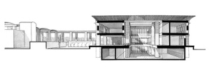
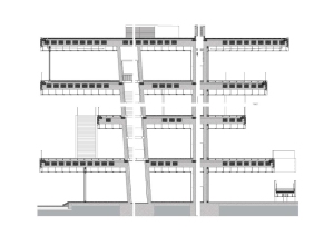
Here are just a few examples of existing section drawings, just to get an idea as to the elements they require; Once a section rendering has been produced it is quite a visually satisfying thing to look at.
Interior Sections
Orchid House, Andres Remy Architects


Americas’ cup building ‘Veles e Vents’ Valencia, 2005-2006


Anchorage Museum at Rasmuson Center, Alaska, 2003 – 2009


For more amazing examples of the successes of plans, elevations and sections have a look at David Chipperfield Architects, a firm of architects with a diverse international portfolio of work such as cultural, residential, commercial, leisure and civic projects as well as master planning exercises.
Self directed work
Following the lesson on sections, it was then our turn to have a go at drawing our own. We draw a room in plan and section at 1.100. adding a scaled persons dimensions, the scale and labels.
Room dimensions – 10000mm x 10000mm; Height – 4000mm; Step Height – 200mm; Height of window; 2500mm, finished 3500mm.
Following these dimensions i was able to construct my first to scale section drawing!

For the second part we then had to draw a detailed room section at 1.25 with the dimensions:
Room dimensions -7800mm; Height – 2800x2800mm total 5850mm; step height – 200mm


Learning to draw a section to scale is very important as a designer, as this will be a basic requirement if we are constructing a plan for a client. Of course i am quite rusty at the moment and it does take quite a lot of time and thinking to make a plan like this, but after doing this a number of times i think i will get the hang of it and eventually to be able to create a section rending quickly and effectively.

One Reply to “”